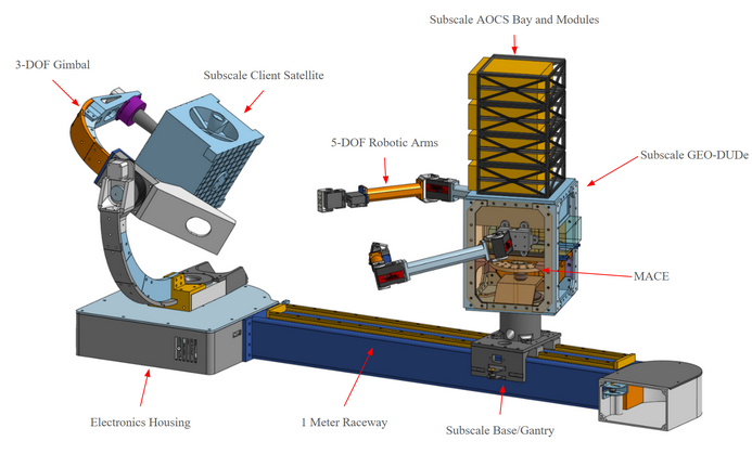
Overview
My role in this capstone was to design and simulate the complete Attitude and Orbit Control System (AOCS) for GEO-DUDe, an autonomous on-orbit servicing spacecraft tasked with rendezvous, proximity operations, and docking with a defunct geostationary satellite. The AOCS was built in MATLAB and Simulink through progressive iterations: starting from a simple rigid-body dynamics model with an ideal controller, then adding realistic actuator models, disturbance torques, sensor noise, and state estimation in successive layers, validating each addition before building on it.
The project also included a physical sub-scale docking simulator. My responsibility on the hardware side was tuning the 1D reaction wheel, iterating on controller gains through bench testing until the system reliably locked orientation onto the client satellite mock-up during the docking demonstration.
Spacecraft Dynamics
Development started with a basic rigid-body dynamics model using Euler's equations of motion, driven by ideal torque inputs to verify the kinematics before adding actuators. Early runs with Euler angles exposed gimbal-lock issues during large-angle manoeuvres, which drove a switch to a full quaternion representation — quaternion kinematics propagate attitude from angular velocity, Euler's equations propagate angular velocity from applied torques, with no singularities at any attitude.
Reaction Wheel Model
Once base dynamics were validated, a four-reaction-wheel model in a pyramidal configuration was added. The first version treated wheels as ideal torque sources; after validating basic control authority the model was refined to include individual moments of inertia, spin rate limits, torque saturation, and wheel angular momenta coupled into the spacecraft's total momentum budget. Saturation events that appeared during extended simulation runs then drove the addition of thruster-based momentum dumping to keep wheel speeds bounded over the full mission duration.
Wheel Configuration
A pyramidal four-wheel arrangement was selected — three wheels provide primary 3-axis control, the fourth provides redundancy against a single-wheel failure.
Torque Allocation
A pseudo-inverse mapping distributes the commanded 3-axis body torque across the four wheels, minimising wheel speed while meeting the torque demand.
Thruster Desaturation
Desaturation logic fires thruster pairs to dump stored angular momentum when wheel speeds approach saturation, while the wheels compensate for the resulting body torque.
Thruster Model
Attitude thrusters are modelled as on/off devices with fixed thrust and moment arms, with a PWM scheme converting continuous torque demands into thruster fire times.
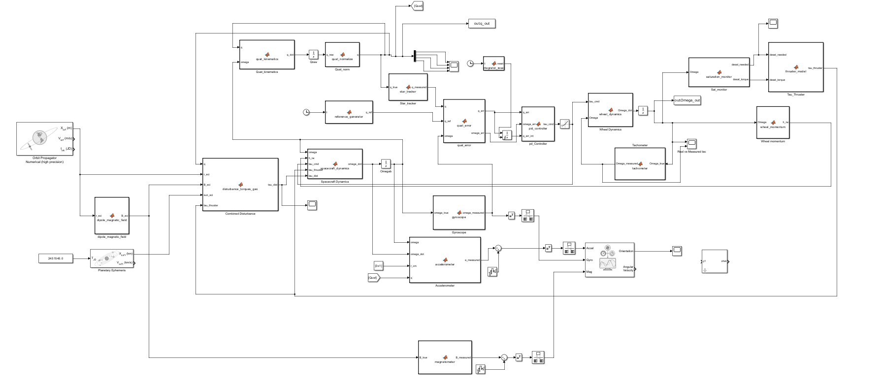
Figure 2 - Simulink model showing rigid-body dynamics, reaction wheel coupling, and actuator interfaces.
Disturbance Environment
With the dynamics and actuator models validated, environmental disturbance torques were added incrementally starting with gravity gradient (dominant for GEO-DUDe's elongated geometry), then solar radiation pressure, magnetic torque, and aerodynamic drag. Adding each disturbance in isolation revealed its effect on steady-state pointing error and wheel speed build-up before layering the next, making it clear which terms were driving the station-keeping and desaturation requirements.
Gravity Gradient
Computed from the inertia tensor and local vertical — the dominant disturbance torque for GeoDude's elongated geometry due to the variation in Earth's gravitational field.
Solar Radiation Pressure
Photon pressure torque on the solar arrays and bus surfaces, modelled as a function of surface area, reflectivity, and the offset between centre of pressure and centre of mass.
Magnetic Torque
Interaction between the spacecraft's residual magnetic dipole and Earth's field. Small at GEO but included to keep the simulation accurate.
Aerodynamic Drag
Negligible at GEO but modelled to keep the simulation extensible to lower-orbit mission scenarios.
Sensor Selection
Sensor selection was driven by the accuracy, update rate, and fault-tolerance requirements of a GEO rendezvous mission. The goal was a three-sensor suite that provides high-accuracy steady-state attitude knowledge, high-rate propagation between updates, and an independent coarse reference for initial acquisition — without relying on any single measurement source. Each sensor was evaluated against its noise characteristics, GEO availability, and how well it complemented the others before being incorporated into the simulation.
Selected Sensors
Star Tracker
Selected as the primary attitude reference for its arc-second accuracy and quaternion output. Low update rate makes it unsuitable for high-bandwidth control alone, but ideal as the high-accuracy anchor for the state estimator.
Gyroscope (IMU)
Chosen for its high sample rate to propagate attitude between star tracker updates. Bias drift over time was the key limitation — addressed through the state estimator rather than by switching sensors.
Sun Sensor
Included as an independent coarse reference for initial acquisition and safe-mode recovery, when the star tracker may not yet be converged or available.
State Estimator
With the sensor suite defined, a nonlinear state estimator was designed to fuse all three measurements into a single optimal attitude and rate estimate. The state vector covers quaternion attitude, angular rate, and gyroscope bias. Because quaternion kinematics are nonlinear, the estimator linearises at each timestep via the propagation Jacobian. Star tracker and sun sensor updates correct accumulated gyro drift, and process and measurement noise covariances were tuned against sensor datasheets through several iterations to achieve well-conditioned innovations throughout the simulation.
Control Law
The control law went through the most iteration of any component. Development started with a simple proportional controller on quaternion error — working in quaternion space from the outset to avoid the singularities that had already caused problems in the dynamics model. Once basic stabilisation was confirmed, a derivative term on angular rate was added, and both gains were tuned in simulation against pointing accuracy and slew rate targets.
Reaction Wheel Control
Gain tuning with the full disturbance and sensor noise model in the loop revealed that a linear PD gain was insufficient for large-angle slews — wheel torques saturated before the manoeuvre completed. A nonlinear gain scaling was added to reduce the proportional term during large slews and keep torques within hardware limits, then restore full bandwidth for fine pointing. Multiple tuning rounds were needed to balance slew speed against saturation margin across the full range of manoeuvres required during rendezvous operations.
Closed-Loop Performance
Final verification ran the fully integrated model dynamics, disturbances, sensor noise, state estimator, and both control modes across three scenarios: steady-state pointing under continuous GEO disturbances, a 90° slew manoeuvre, and wheel desaturation while holding attitude. Each scenario exposed remaining issues that fed back into one more round of gain or covariance adjustment before the design was locked. Performance was evaluated against pointing error, slew time, and peak wheel speed to confirm the system met mission requirements.
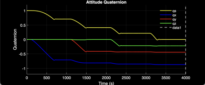
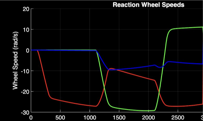
Figures 6-7 - Quaternion error convergence during a slew and wheel speeds throughout the manoeuver.