Design
As controls lead I designed the ACS a canard-based roll stabilization system that nulls the spin Argus experiences during ascent. The spin is an unintended consequence of manufacturing defects in the large static fins that can drive the rocket to hundreds of RPM. I chose roll control specifically because the worst-case failure mode (no actuation) leaves the rocket behaving like any passive uncontrolled rocket, minimizing the risk of catastrophic failure from an erroneous command.
This page outlines my specific contributions towards the design of the canard bay, due to the relatively high skill curve in regards to control system design a bulk of the work fell on myself and 2 others. Overall the project was a sort of capstone in itself requiring extensive knowledge and research of aerodynamics, matlab, Simulink, 3D design and Mechanical simulation. Not only did provide a practical application of my Aerospace education over the last 4 years it also expanded my knowledge and skill base far beyond what was originally taught in lectures and labs
Canard Bay
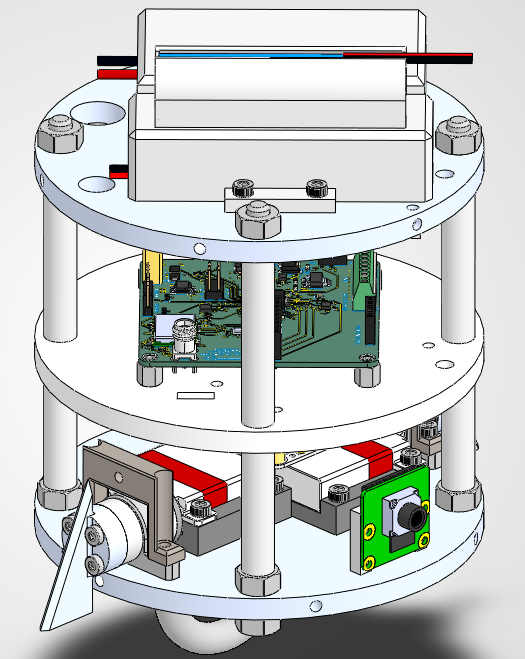
The canard bay design was led by myself and involved heavy use of iterative design 3-D printed test components. The canard bay itself was designed house the PCB, batteries, the Servos and the canard actuation mechanism. This design was a ground up redesign with knowledge gained from a test launch preformed in late March. The design process was conducted within SolidWorks with analysis being preformed in ANSYS.
The largest constraint in the design process was the size limitations both in diameter and length. The rocket only had an inner diameter of 4.8in which mainly caused issues with the canard actuation mechanism since the servos took up a large amount of space. This lead to many different design changes, such as opting to go for a direct drive configuration where the servos are connected to the canards with only a shaft vs a geared mechanism. Of course DFM played a heavy roll in the design process, care was taken to follow DFA/DFM best practices, and ensuring all components can be either purchased commercially or can be reliably manufactured or machined. The final design of the Canard bay involved 3 bulkheads the top and bottom ones being made from Al-6061-T6 while the middle bulkhead was 3-D printed from PET-G. The top and bottom bulkheads were fastened to the airframe with screws and were designed to take structural loads.
I designed the canard actuation mechanism as four parts per canard: a servo shaft adapter (connecting the servo horn to a 7 mm shaft), a pillow bearing (offloading axial servo loads), an angle limiter (hard-stopping deflection at ±10°), and a canard plate that the fin bolts into. The mechanical limit gives a hardware stop independent of software canards cannot over-deflect under any fault condition.
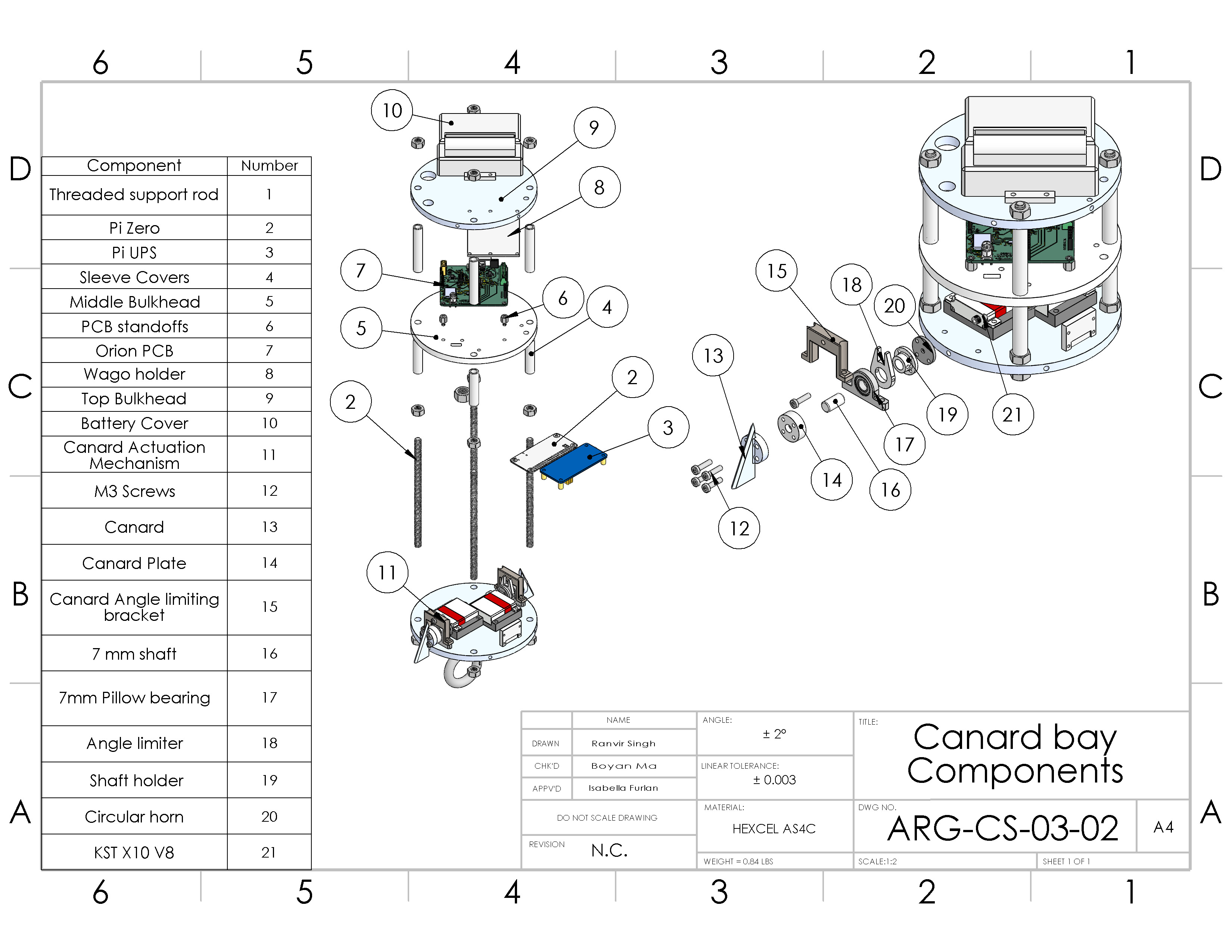
Figure 2 - Exploded view of design.
Canard Sizing
I sized the canards against two primary constraints: Mach angle and control authority.
Mach angle: As Argus accelerates through transonic and into supersonic flight, the shockwave cones from the nosecone narrow. I applied the Mach angle equation to find the critical sweep at max velocity a minimum of 25°, requiring a canard sweep exceeding 65° to avoid a supersonic leading edge and its associated drag and uneven spanwise loading.
Control authority: I wrote a MATLAB script to compute angular acceleration about the roll axis as a function of canard geometry, using Hembold’s equation for subsonic CLα and an empirical supersonic derivation across the velocity profile extracted from OpenRocket. My sizing target was nulling a 4 Hz roll rate drawn from prior MetRocketry launches in under 1 second at any point in the flight envelope. The final geometry I settled on 40 mm root chord, 18.5 mm span, 10° max angle of attack achieves a time-to-null of 0.644 s.
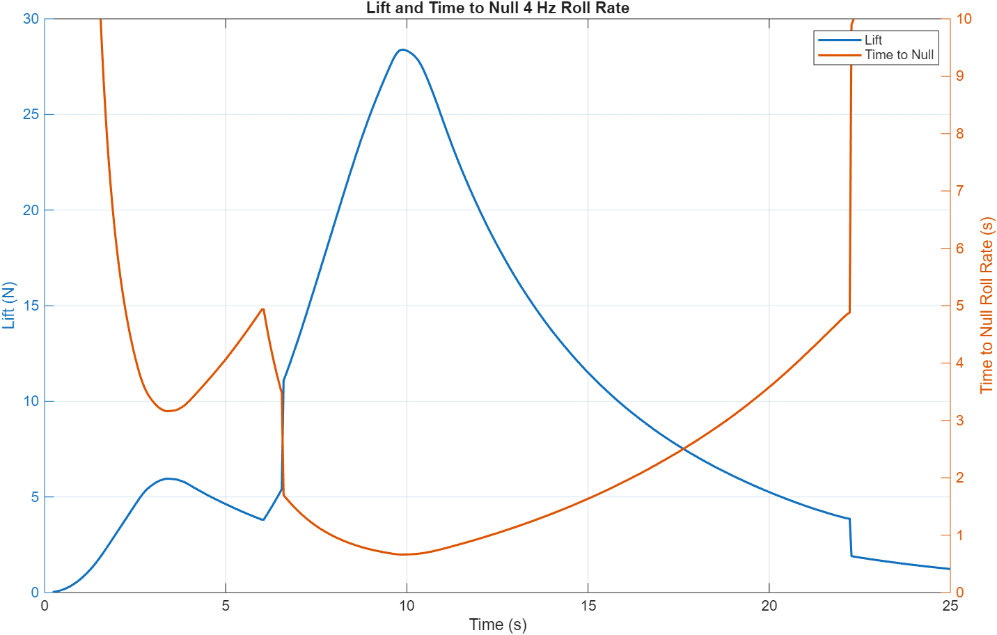
Figure 2 - Time to null a 4 Hz roll rate across the flight velocity range for the selected canard geometry.
Structural Validation (FEA)
I ran FEA in ANSYS Mechanical to verify the actuation mechanism under a conservative worst-case canard load of 150 N more than 3× the calculated peak of ~40 N. The minimum safety factor of 1.94 occurred on the shaft, comfortably above the 1.5 aerospace standard, confirming the structure is adequate across the full load envelope.
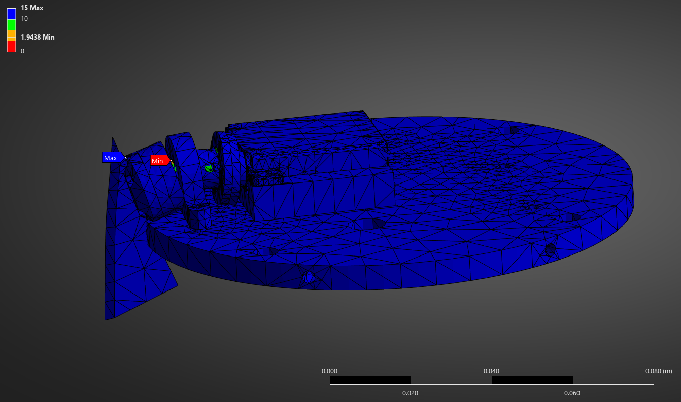
Figure 3 - ANSYS Mechanical stress distribution on the canard actuation shaft under 150 N worst-case load.
Aerodynamic Analysis (CFD)
I ran an extensive CFD campaign to characterise canard normal force as a function of deflection angle and flight velocity. I swept deflection angles from 1° to 10° across velocities spanning subsonic through Argus's expected maximum. At each velocity the deflection–force relationship is approximately linear; I extracted the slope as a control coefficient, plotted it against velocity, and fit three separate polynomials one per sonic region for use in the controller.
I also derived an altitude scaling factor by running simulations at fixed velocity and deflection while varying pressure, then fitting a logarithmic curve to the resulting force-ratio vs. altitude. For example, a 5° deflection at 100 m/s produces 5 N at sea level but only 3.5 N at 10,000 ft (effectiveness 0.7), so I scale the control coefficient by the inverse (1.42) to maintain the demanded lift force. This gives me effective gain scheduling across the full flight envelope without a large multidimensional lookup table.
6DoF Simulation
I developed a six-degree-of-freedom flight simulation in MATLAB/Simulink as the primary environment for controller tuning and verification. I roughed in the controller first on a simpler 3DoF Simulink solver with simulated Gaussian sensor noise, then ported it into the full 6DoF model with aerodynamics, thrust curves, and atmospheric variation for final tuning before embedded implementation.
Model Architecture
I built the model to capture full rigid-body translational and rotational equations of motion, with aerodynamic forces and moments pulled from my CFD control coefficient data and OpenRocket aero tables. I tabulated and interpolated motor thrust curves, modelled atmospheric density and pressure as functions of altitude, and added Gaussian noise and gyroscope bias to the sensor models letting me test the Kalman filter and controller against realistic measurement conditions.
I identified accurate servo modelling as critical for realistic tuning I characterised the servo transfer function separately and incorporated it into the sim so that bandwidth limitations and command lag show up in the closed-loop results.
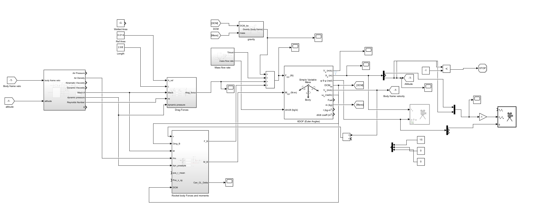
Figure 6 - Top-level Simulink block diagram of the 6DoF flight model with ACS loop closed.
Controller Tuning & Verification
With the full 6DoF aerodynamic environment in the loop, I tuned the PD gains against roll rate convergence time and overshoot targets. The sim confirmed that my controller nulls a 4 Hz initial roll rate within the 1-second budget across the post-burnout flight regime, while keeping canard deflection inside the ±10° mechanical limit.
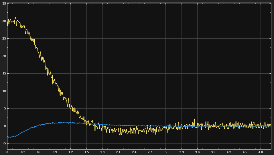
Figures 7 - Simulated roll rate nulling and corresponding canard deflection history.
Sensitivity Analysis
I performed a sensitivity analysis by perturbing key parameters within realistic bounds and measuring the effect on roll rate convergence time, overshoot, steady-state error, and attitude tracking accuracy sweeping IMU noise and bias, barometer noise, an accelerated thrust curve (higher-than-predicted peak velocity), and servo response time.
The controller and state estimator proved robust to sensor noise and aerodynamic variation. The dominant sensitivity I found was servo response time a slower servo (from friction or high aerodynamic loading) ranged from delayed roll-rate response to full destabilisation in the high-Mach regime near max-q where small precise deflections are required. That finding directly drove my servo selection and torque-margin requirements.
Control System
I structured the ACS around two main components: a state estimator providing real-time roll angle and roll rate, and a torque-based PD controller that drives the canards to zero both quantities. A deliberate design principle I followed was keeping the controller itself linear and simple, offloading all aerodynamic nonlinearity into a separate control coefficient look-up derived from CFD reducing MCU computational load and keeping tuning tractable.
State Estimation
I implemented two Kalman filters running in parallel. A Linear Kalman Filter (LKF) handles altitude estimation by fusing accelerometer and barometer data the accelerometer propagates altitude and vertical velocity, while the barometer provides an independent measurement via the barometric formula. Vertical dynamics are approximately linear over small timesteps, making an LKF sufficient here.
I implemented an Extended Kalman Filter (EKF) for attitude estimation, fusing gyroscope, accelerometer, and magnetometer readings. Attitude kinematics are inherently nonlinear, so I linearised the system via a first-order Taylor Series expansion at each timestep. I represent orientation as a quaternion rather than Euler angles to prevent gimbal lock. The gyroscope integrates angular velocity for orientation but accumulates bias over time; the EKF corrects this drift using the accelerometer and magnetometer as independent references.
Controller & Control Coefficient
I designed a static torque-based PD controller that observes roll rate and roll angle from the EKF and outputs the torque demand needed to correct both errors. I kept the controller intentionally linear it does not directly account for aerodynamic effects, which I handle separately through the Control Coefficient.
The Control Coefficient is the set of polynomial equations I derived from the CFD campaign. Given the current flight velocity, the controller evaluates the appropriate polynomial (one of three, one per sonic region) to get the control force coefficient, converts the torque demand to a required force via the canard moment arm, and divides by the coefficient to yield the deflection angle command. I apply an additional altitude scaling factor a logarithmic curve I fit to CFD results at varying pressures to account for decreasing air density at altitude. Together, these steps replicate gain scheduling across the full flight envelope without a large multidimensional lookup table or re-linearisation at each operating point.
Roll Angle Error
Proportional term drives the canards to return the rocket to 0° roll, providing restoring force proportional to how far the rocket has rotated.
Roll Rate Error
Derivative term damps out spinning before it accumulates into a large angle error, providing the bulk of active stabilisation authority.
Torque → Deflection
The torque output is converted to canard deflection via the CFD-derived control coefficient and altitude scaling, accounting for varying aerodynamic effectiveness.
Deflection Limiting
Software clamps commands to ±10°; mechanical angle limiters provide a hard backstop independent of software state.
Flight Software
I wrote the flight software on FreeRTOS around a state-machine architecture. On power-up, I initialise hardware buses and peripherals before the scheduler starts. A high-speed sensor reading task feeds a launch detection task that tracks flight state:
- Launch detection: IMU acceleration exceeding 4 G for 100 ms triggers liftoff and enters the boost state.
- Burnout detection: After waiting ~10.9 s for the motor to finish, a sharp drop in acceleration confirms burnout.
- ACS activation: On burnout confirmation the canards deploy and the PD controller takes over.
- Safety cutoff: If pitch error exceeds 30°, the high-side switch cuts servo power preventing actuation under an anomalous flight attitude.
Throughout all phases, I log state estimation and sensor data to an onboard SD card and transmit live attitude and altitude data to the ground station over a 433 MHz LoRa link for real-time monitoring and post-flight analysis.